Making a Display Unit in lieu of an MCB44.
The control panel of an Elliott 920B or 903 computer has a row of 18 hand keys. These are used to select the starting point of a program in memory, and can also be used to insert programs or data into memory. But there is no corresponding row of 18 lights, to read out results or the contents of memory. So, whilst the control panel is essential in program development, it is of very little help in locating hardware faults.
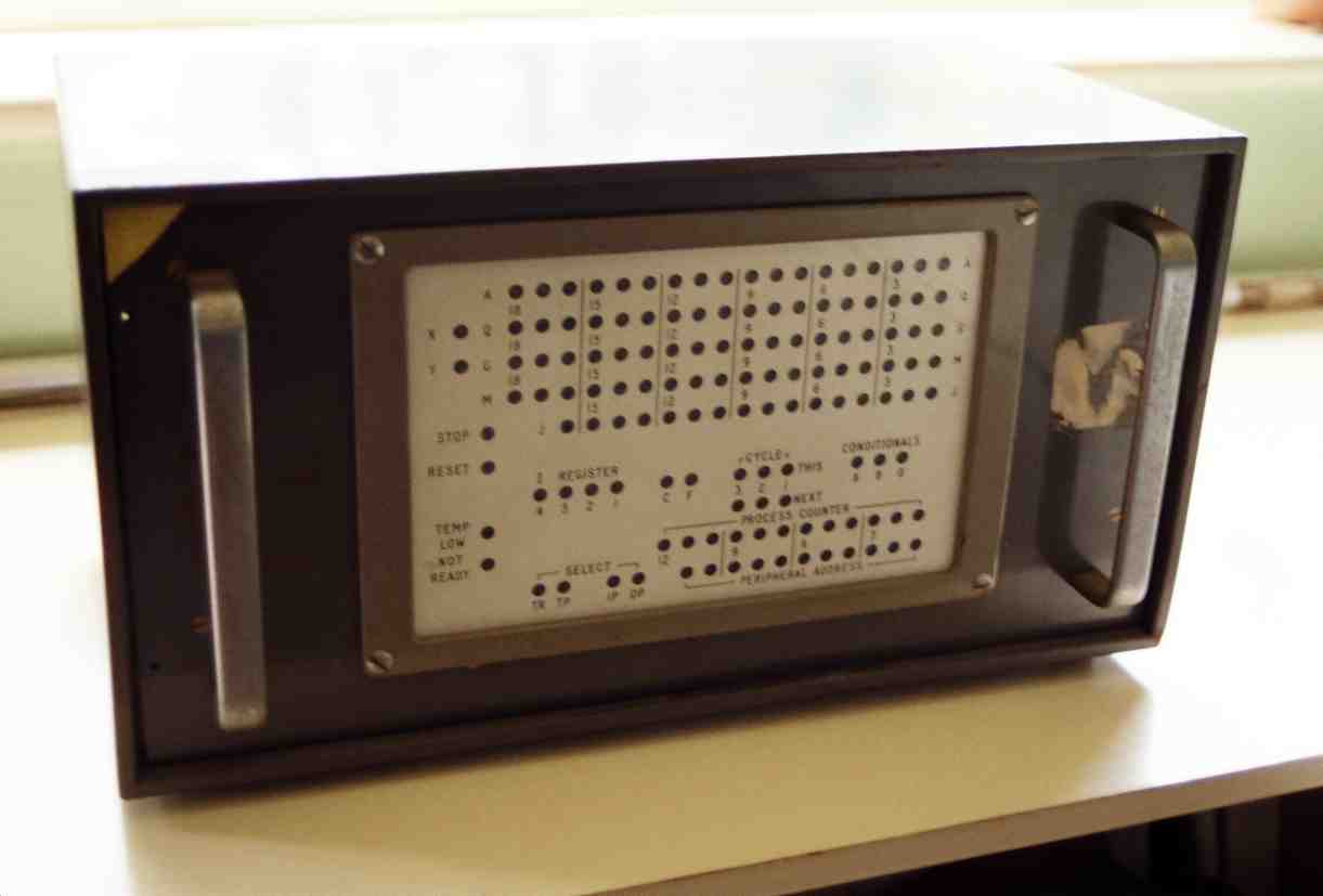
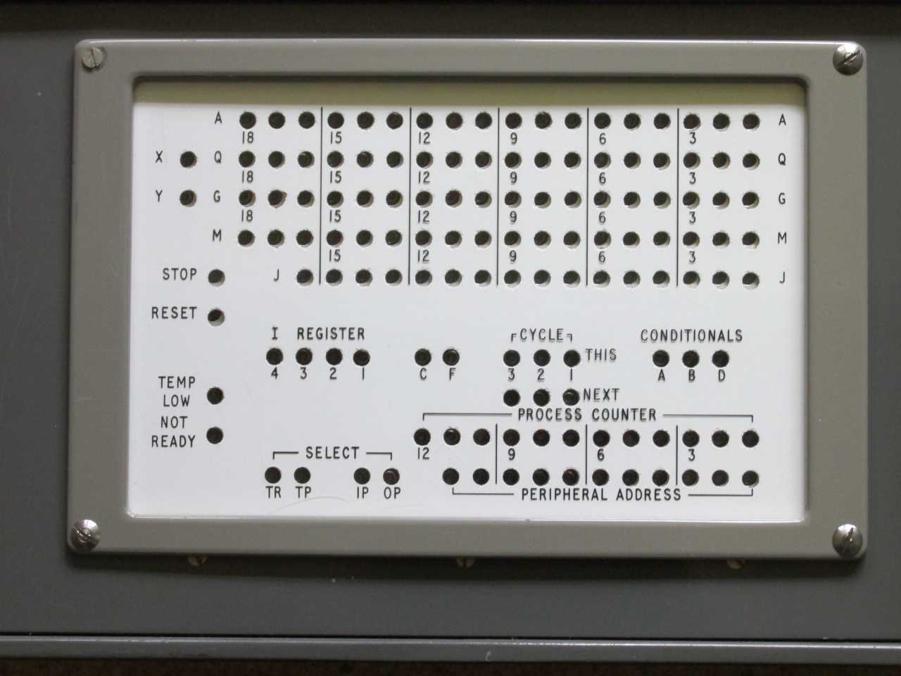
For troubleshooting on a 920B or 903, engineers use a separate portable MCB44 Display Unit, which simultaneously displays the contents of several registers on neon lights, seen here and in close-up here. The display unit is connected to the computer using three cables with 61-way connectors. The display derives the high voltage needed to drive the neons from the processor’s 6-volt supplies and an internal inverter.
One minor problem is that the neons on the display Unit are closer together than the keys on the control panel, so the two don’t line up when you stand one unit on top of the other. The later Elliott 920C or 905 control panel does have a built-in row of 18 lights, and a rotary knob which enabled the contents of just one chosen register to be displayed, and here the keys and lights do line up.
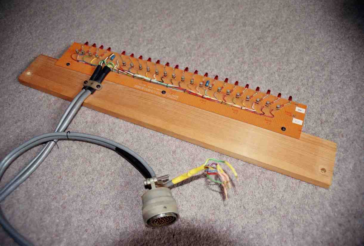
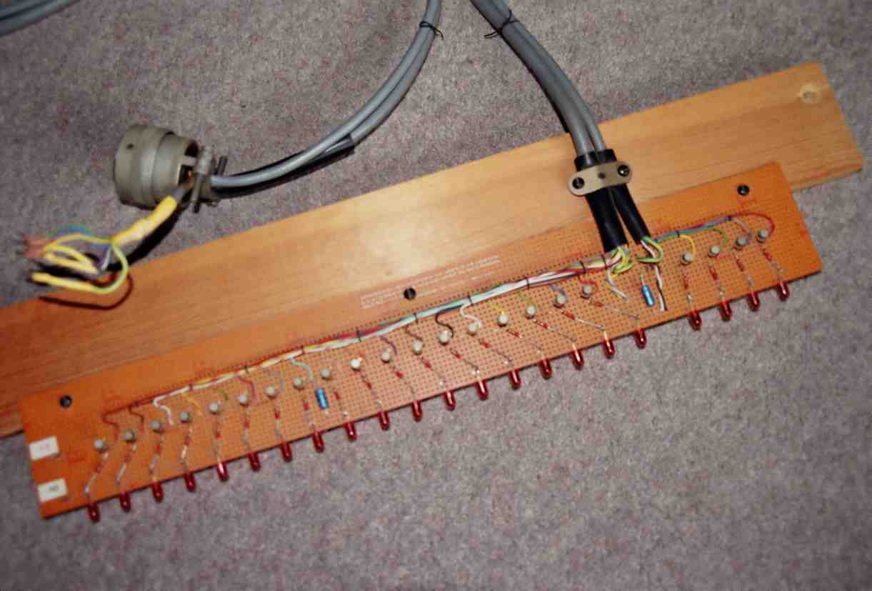
When I first acquired my Elliott machine it was not working and I had no MCB44. Initially I got it working using a multimeter and a logic probe. But to help me keep it working, I built my own minimal LED display unit, seen here and here. I wrote some wiring notes at the time. (I did get an MCB44 some years later, but I still don’t have the three cables with those expensive 61-way connectors on each end, so I have no idea if my MCB44 is working).
Luckily I did have one 61-way plug. The shells of the 61-way circular plugs have keyways, to ensure that the plugs are inserted with the correct orientation into the sockets. To avoid confusing the three plugs, the orientation of the pins relative to the shells in each of the three cables is different. But the layout of the 61 pins within the plug is identical. My first task, then, was to file the keyways off the outside of my plug, so I could fit it into the most useful of the three processor sockets, which is SK1.
SK1 carries all 18 accumulator ('A' register) bits. I used a 20-core screened cable to connect to these 18 bits with the screen connected to mains earth. (The spare 2 cores are wired to the overflow bistables X & Y at the processor end but are unused at the display end). Power is only available on SK3, so I used another, 8-core, screened cable to connect to 0volt and +6volt on SK3 (using two cores each) with the screen connected to mains earth. The remaining 4 cores are usefully connected to the 4 bit function field of the current instruction ('I' register), which is also on SK3. These connections are made by inserting 7 loose pins carefully into SK3, and these are held in place by clamping the two cables together.
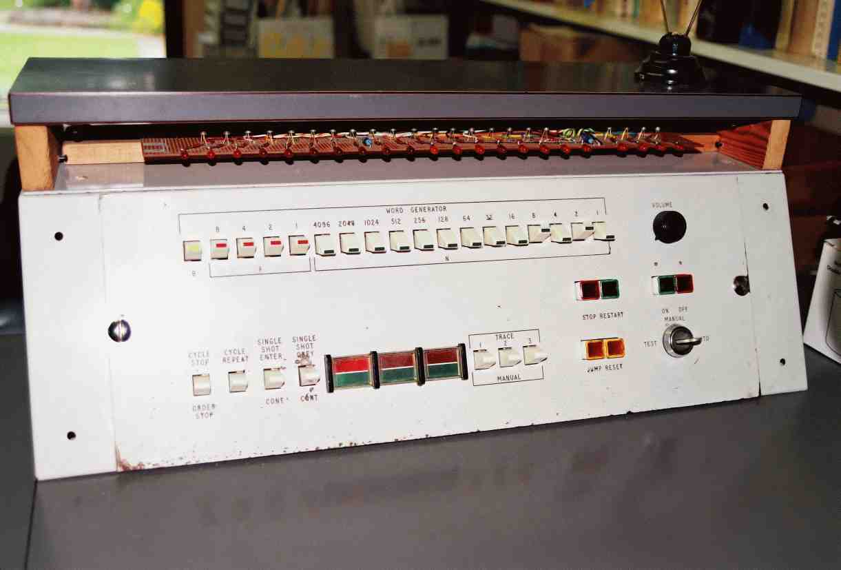
The display consists of 22 identical circuits each comprising a BC478 transistor, a 270ohm resistor, and a LED. The processor sockets give "bar" (inverted) outputs: low for 1, high for 0. Using a PNP transistor puts the signal the right way up, so that the LEDs are on for 1 rather than 0. The circuit is built on stripboard with the transistors 0.6 inches apart. The LEDs are pushed onto the side of the stripboard (and soldered to the 0volt rail) rather than using the holes on the stripboard, so that they can be the same distance apart as the keys on the control panel (which is about 0.69 inches, both on my re-arranged control panel and on an unmodified one).
The unit can be seen under the (raised) cover of my control panel, with the 18 accumulator LEDs over the 18 keys and with the 4 function LEDs to the right over the volume control. QED. And for those purists who might object to my fitting 1970s technology onto a 1960s computer, the whole unit is easily removed should the need arise.